Collimating Lenses for Spectrometers & Optical Fibers
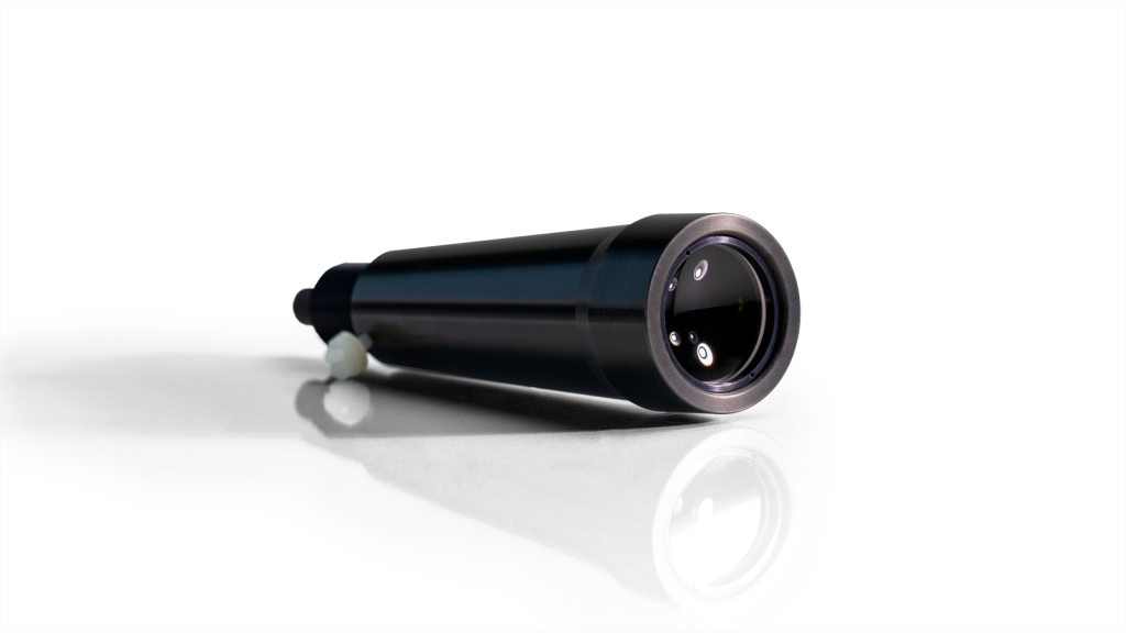
Collimating lenses are optical lenses that make parallel the light beams that enter your spectrometer setup. These lenses allow users to control the field of view, collection efficiency and spatial resolution of their setup, and to configure illumination and collection angles for sampling.
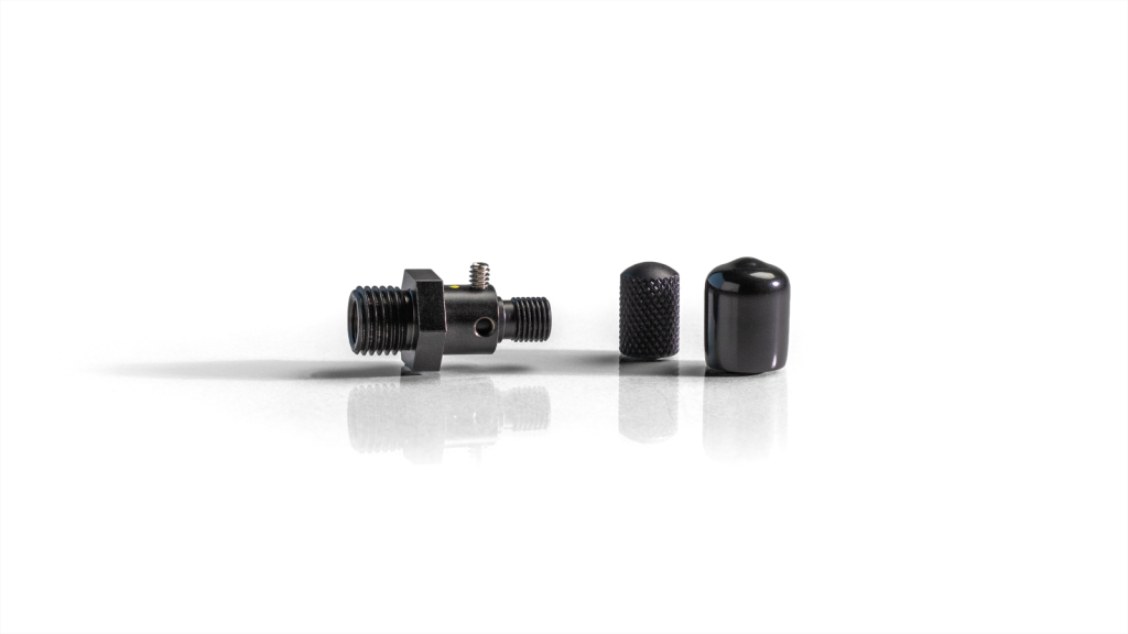
Ocean Optics collimating lenses can be attached to the spectrometer, coupled to optical fibers, or integrated into sampling accessories. Most lenses have an inner barrel threaded for SMA 905 connectors. The inner barrel slides relative to the lens fixture for adjusting the focus; a setscrew secures the barrel.
74-ACR
Connect to optical fiber
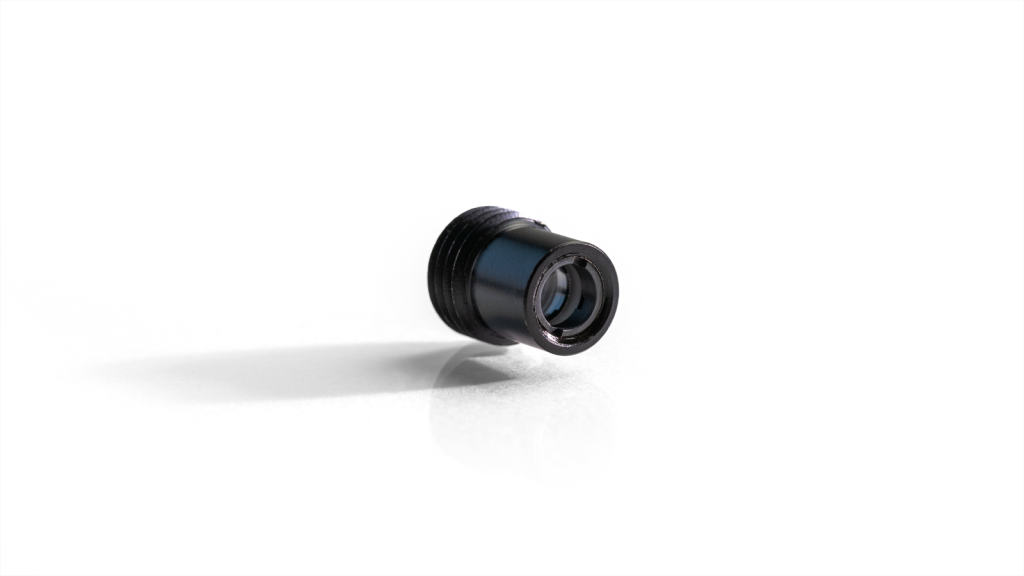
74-DA
Direct attach to spectrometer
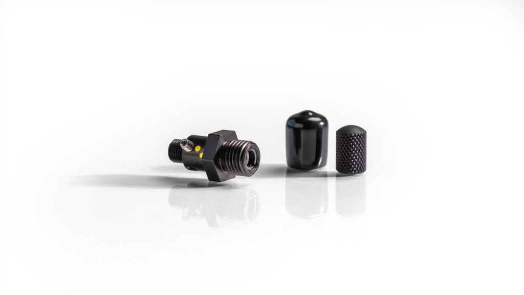
74-UV
UV collimating lens connects to optical fiber
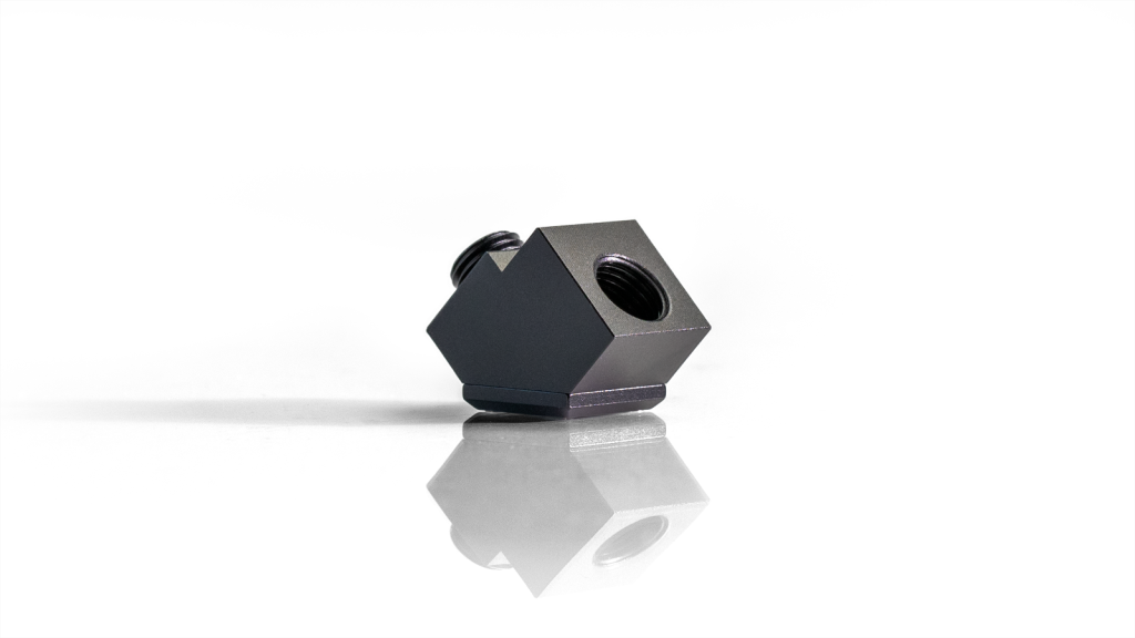
74-90-UV
Reflects light from the collimating lens to 90°
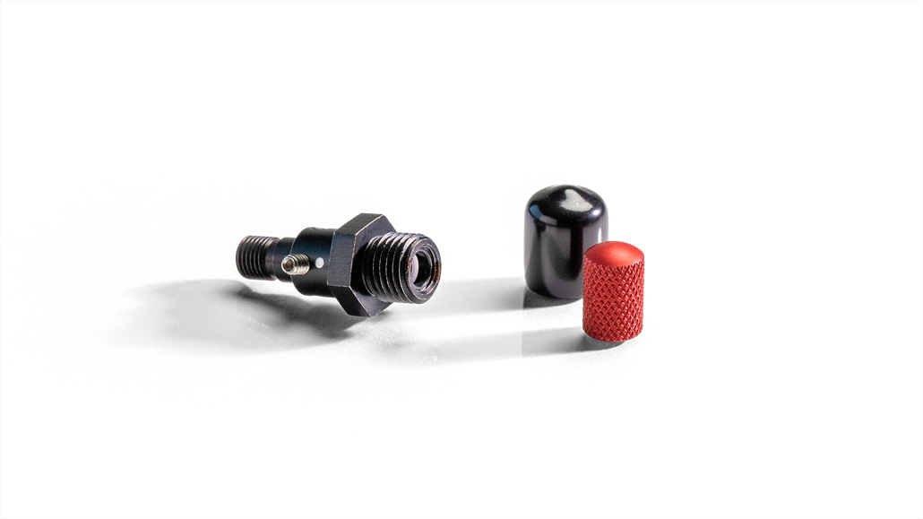
74-VIS
Vis collimating lens connects to optical fiber
84-UV-25
Collimate light at long distances in open air
| Specifications | 74-ACR | 74-DA | 74-UV | 74-90-UV | 74-UV-HT-VAC | 74-VIS | COL-UV-30 | 84-UV-25 |
| Type | Achromatic doublet | Single lens direct attach | Single lens | A mirror under the cap reflects light from the collimating lens at a 90° angle | Specialty lens for high temperature, high pressure vacuum applications | Single lens | Largest-diameter lens | Single lens |
| Connects To | Optical fiber | Spectrometer | Optical fiber | Optical fiber | Optical fiber | Optical fiber | Optical fiber | Optical fiber |
| Lens Material | f/2 BaF10 and FD10 fused silica | f/2 fused silica | f/2 fused silica | f/2 fused silica | f/2 fused silica | f/2 BK-7 glass | f/2 fused silica | f/4 fused silica |
| Wavelength Range | 350-2000 nm | 200-2000 nm | 200-2000 nm | 200-2000 nm | 190-2000 nm | 350-2000 nm | 200-2000 nm | 200-2000 nm |
| Connector | SMA 905 6.35 mm ferrule | SMA 905 | SMA 905 6.35 mm ferrule | SMA 905 6.35 mm ferrule | – | SMA 905 6.35 mm ferrule | SMA 905 6.35 mm ferrule | SMA 905 6.35 mm ferrule |
| Connector Threads | 3/8-24 external thread | 3/8-24 external thread 1/4-36 internal thread | 3/8-24 external thread | 3/8-24 external thread | 3/8-24 external thread | 3/8-24 external thread | ¼-36 external thread | ¼-36 external thread |
| Diameter | 5 mm | 5 mm | 5 mm | 5 mm | 5 mm | 5 mm | 30 mm | 25.4 mm |
| Focal Length | 10 mm | 10 mm | 10 mm | 10 mm | 10 mm | 10 mm | 30 mm | 100 mm |
| Operating Temperature | 150 °C | 150 °C | 150 °C | 120 °C | 250 °C | 150 °C | 200 °C | 70 °C |
We Are Here to Help
Regulatory
Standards, Terms & Conditions, and More.

Customer Support Hub
Product Info, Tech Support, Returns and More.